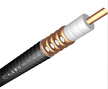
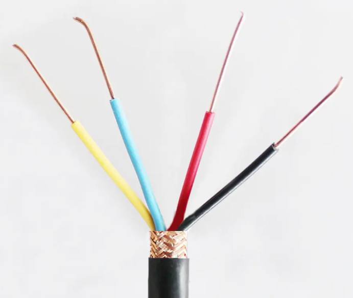
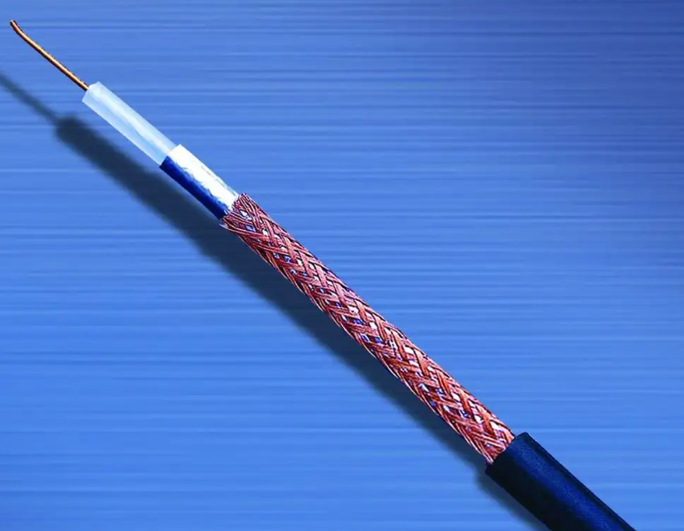
Leaky cable is short for leaky coaxial cable. Having both the function of transmitting signals and an antenna through the control of a conductor opening. The controlled electromagnetic wave energy can be radiated out and received evenly along the road to realizing the coverage of the electromagnetic field blind area, which has achieved the purpose of unobvious mobile communication.

Cables are mainly used for wireless communication in the environment or blind area where radio waves are not good to propagate, such as tunnels, high-speed railways, rail transit, highways, mines, and warning systems for tall buildings, which have the characteristics of large transmission power, low voltage standing wave ratio and low loss.
The insulation layer adopts the uniform fine closed microtubule structure with high physical foaming because compared with the traditional air insulation structure, the transmission parameters such as characteristic impedance, standing wave coefficient and attenuation are more uniform and stable.
It can also resist the intrusion of moisture into the cable in a humid environment, which may cause the decline or loss of transmission performance. It eliminates the trouble of inflation maintenance, greatly improves the service life and excellent stability of the product. It is a more advanced RF and leakage cable structure in the world today.
Transverse electromagnetic waves are transmitted through a coaxial cable from the transmitter at the other end of the cable. When the outer conductor of the cable is completely closed, the signal transmitted by the cable is completely shielded from the outside world, and there is no electromagnetic field outside the cable, or electromagnetic radiation can not be evaluated. Similarly, the external electromagnetic field will not affect the signal inside the cable.
However, a portion of the electromagnetic energy transmitted in the coaxial cable is sent to the external environment through a slot in the outer conductor. In the same way, external energy can be passed into the cable. The grooves in the outer conductors couple the electromagnetic field inside the cable with the external electric waves.

A typical example of a leaky cable is a coaxial cable with a woven outer conductor. Most of the energy is referred in the cable in the form of internal waves. However, surface waves are generated at locations where the outer conductor is not properly covered, which propagate outward in the forward or reverse direction along the cable and interact with each other.
The quality of radio communication signals usually varies greatly owing to the fluctuation of the electrical wave level outside the cable. The mode and environment of cable laying also affect the radiation effect of cable. Longitudinal attenuation constant and coupling loss is the main indexes of the electrical performance of the leaking coaxial cable.
The coupling loss describes the index of the energy generated by the coupling outside the cable and received by the external antenna. It is defined as the ratio of the energy received by the external antenna to the energy transmitted in the cable at a definite distance. Since the influence is reciprocal, a similar method can be used to analyze the signal transmission from the external antenna to the cable.
The coupling loss is influenced by the cable slot type and the interference or reflection of the signal from the external environment. Over a wide range, stronger radiation means lower coupling losses. According to the different coupling mechanism between the signal and the outside world, there are the following three types of leaky cables:
Radiant
Coupling type
This section of leaky cable is equivalent to a positioning antenna connected to a coaxial cable through a power divider. Only a small fraction of the energy inside the cable is transformed into radiant energy. The appropriate spacing between adjacent leakage segments is chosen to provide satisfactory results for different frequency bands. Under the same conditions, the leaky cable designed in this way can serve as a continuous compensation feeder, and has better attenuation constant and coupling loss characteristics.
The attenuation constant is the principal characteristic to evaluate the energy loss of electromagnetic wave transmission in cable. The signal inside a shared coaxial cable gets weaker with the distance at a certain frequency. The attenuation performance depends on the type of insulation layer and the size of the cable.
In the case of a leaky cable, the surrounding environment also affects the attenuation performance, because a small part of the energy inside the cable is propagated in the outward boundary environment near the outer conductor. Therefore, the attenuation performance is also dependent on the arrangement of the slots in the outer conductor, which is how the leaky cable work.

In order to make sure that the leakage cable can normally transmit wireless signals, we need to know some precautions in advance when installing.
1. When installing two cables, it should be pointed out that they should not be crossed or installed close to each other, and the excess cables should be cut off (including non-leakage cables).
2. When installing the two cables, remember to lay them in parallel. The spacing between the two cables is 1-3 meters, and the best spacing is 1.5 meters.
3. The cable placement attempt depends on the medium. Under normal circumstances, the buried depth of soil is 10-20cm, and the buried depth of cement is 3-7cm.
4. When the two cables are set in parallel, the plane drop is not less than 135 degrees.
5. When installing the two sets of cables, ensure that there is an overlap area of about 3 meters between the end and end of the two adjacent leakage cables, and ensure that there is an interval of about 0.3 meters between the two sets of cables in the overlap area. At the same time, the operating frequency of the main engine of the neighboring two sets of leakage cables should be staggered.
When the host is installed outdoors, it should be noted that waterproof protective box should be in addition to the host.
7. Remember that the power line and signal line cannot be installed close to the leakage cable in parallel, and ensure that the distance between the signal line and the leakage cable should be greater than 30 cm, and the distance between the 220V power line and the leakage cable should be 1 meter away.
8. The standard length of the non-leaking cable connecting the host and the leading cable is 10 meters. Two non-leaking cables should be protected by pipes, which can be PVC pipe or steel pipe. Also, the distance between the two non-leaks should be at least 10cm.

9. The two leakage cables should be loaded into 32MM PVC pipe and buried underground, but remember not to Pierce into the steel pipe.
The buried location of the leakage cable should be more than 2 meters away from the sidewalk and the distance from the road should be more than 4 meters, and if the leakage cable is installed just need to be buried on the side of the wall, should be 1 meters away from the wall.
The above being the installation process of leakage cables. When installing cables, we must be careful and must not be careless, because our carelessness may lead to signalling transmission or cable damage, reduce work efficiency and cause unnecessary losses.